


Mjtronix
Op Amp Tester OTC12 Offset Voltage / Bandwidth Measurements Configuration Tester
Op Amp Tester OTC12 Offset Voltage / Bandwidth Measurements Configuration Tester
Brand: Mjtronix
Type: Op Amp Tester
MPN: OTC12
Country/Region of Manufacture: United Kingdom
Personalise: No
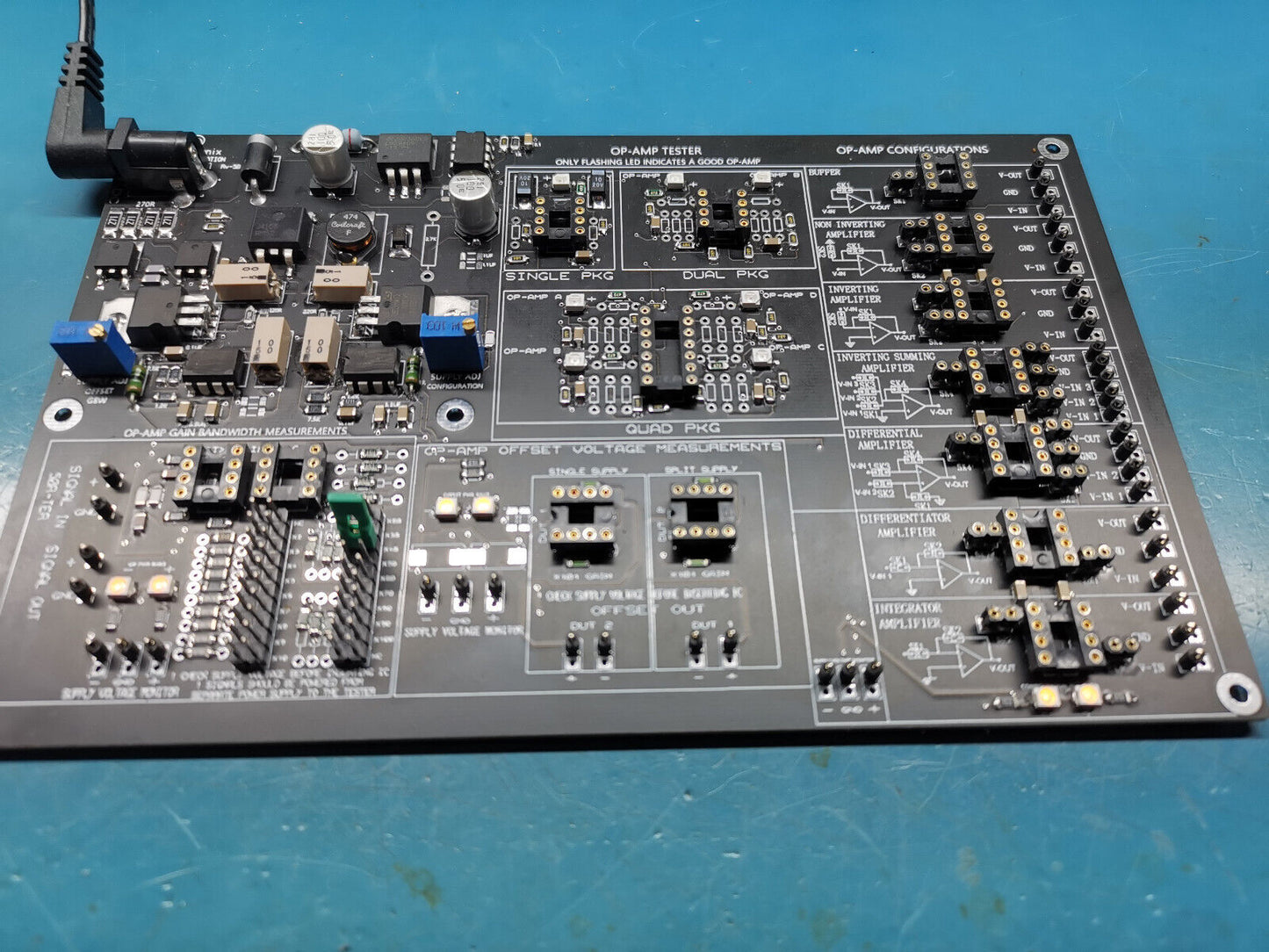
For sale is a OTC12 assembled kit used for testing operational amplifiers. This board has 4 section. each labelled on the PCB with the silkscreen. The unit operates from 12v power supply. Each section has LED for displaying the power rail for that section.
Op Amp Tester:
used to test op amp for functionality. As stated on the PCB only a flashing LED for the corresponding op amp package indicates a working op amps. Any other status indicates a non functioning op amp.
PLEASE NOTE THAT THE SINGLE PACKAGE OP AMP TESTER POWER SUPPLY IS SET TO 12v
Op Amp offset voltage measurements:
the sockets are for single package op amps.
This section is used to measure op amps offset voltages. there are 2 sockets. one for single rail power supply to the op amp and one for split rail power supply to the op amp.
The offset supply adjustment trimmer is used to set the power rail voltage. from 0.5v to around 28v in single rail or +- 13.8v in dual mode. There is a supply voltage monitor pins for connecting multimeter to monitor voltages for the device under test.
for single rail operation the monitor pint will be - and + and for split rail monitor pins will be - GND +. Make sure you set the voltage first before inserting op amp as some op amps have +- 5v or lower max supply and as this section provides over 10v per rail this could damage op amps.
Use the outputs to measure the offset voltage for corresponding DUT. The gain is set to x 101. If an op amp is not designed for single rail power supply operation then inserting it in the single rail socket will display wrong offset voltage out.
Op amp bandwidth measurements:
Please make sure test signal in for this section do not exceed 500mVpp and the sockets are both for single package op amp.
This section is used to measure the gain bandwidth of an op amp. there are 2 sockets one for using op amp in unity gain configuration and other for gains from 1 to 101 . The gain can be selected with the pin headers. each have their gain marked on PCB silkscreen.
for single rail operation the monitor pint will be - and + and for split rail monitor pins will be - GND +. Make sure you set the voltage first before inserting op amp as some op amps have +- 5v or lower max supply and as this section provides up to +-13.8v this could damage op amps.
The signal in is used to feed a sine wave signal in and signal out is used for monitoring the signal gain out. By feeding a signal in and setting a gain and altering the Frequency of the signal you can calculate the gain bandwidth of the op amp. The signal in has not been 50 Ohms terminated. The signal in is AC coupled and the signal out is also AC coupled.
Op Amp Configuration Section:
this section consists of different configuration for single op amp package. the power supply is split rail and can go over 10v per rail.
CHECK SUPPLY VOLTAGES BEFORE INSERTING IC. The input section of these are not AC coupled so if you are feeding AC voltages make sure you AC coupled them first.
The pot to adjust supply voltages for this section is the blue trimmer with supply adj configuration.
make sure the component you use to insert in to the sockets have no solder residue on them as this will damage the sockets.
SIGNALS / AND VOLTAGES NEED TO BE POWERED FROM SEPARATE POWER SUPPLY TO THE TESTER.
PLEASE NOTE THAT THE GBP , OFFSET AND THE CONFIGURATION SECTIONS ARE ALL DESIGNED FOR SINGLE PACKAGE OP AMPS AND NOT DUAL
PLEASE NOTE THESE KITS ARE FULLY TESTED ONCE AFTER ASSAMBELY AND ONCE WHEN SENDING OUT
PLEASE NOTE THERE ARE NO INSTRUCTIONS,CIRCUIT DIAGRAMS OR ANY LITERATURE PROVIDED WITH THIS KIT ,
ALL THE IMPORTANT INFORMATION ARE ON PCB SILKSCREEN. THIS KIT HAS BEEN ASSEMBLED BY HAND AND THE SOLDERING IS NOT 100% PROFESSIONAL.
BOARD DIMENSIONS ARE 195mm X 125mm X 24mm THIS INCLUDES THE TALLEST COMPONENT.
PLEASE ALSO NOTE THAT THERE ARE ALWAYS NEW VERSION OUT WITH IMPROVEMENT SO THE ONE YOU GET MIGHT HAVE DIFFERENT COMPONENT LOCATIONS OR PACKAGE TYPE,
ONLY THE KIT IF IN THIS SALE. THE REST OF THE ITEMS ARE FOR ILLUSTRATION ONLY AND NOT INCLUDED IN SALE. THE OP AMPS INSERTED IN THE TESTER SECTION ARE ALSO NOT INCLUDED THEY ARE FOR TESTING ONLY.
Couldn't load pickup availability
Shipping & Returns
Shipping & Returns
Share


Contact us if you need further info about this product
Please use the item title in all correspondences to aid in answering you question faster