
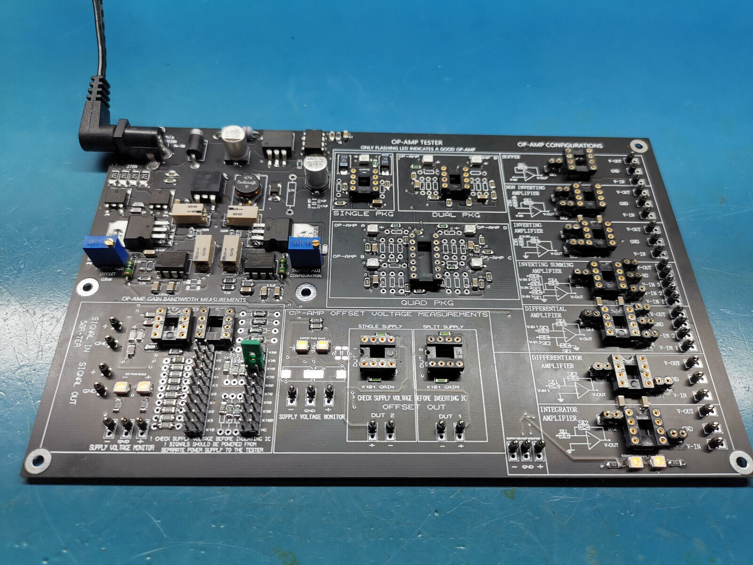
The OTC12 Tester:
The OTC12 tester is used for testing op amps functionality , op amps Gain-Bandwidth Product test , Offset Voltage test and op amps Configurations test . Each section is separated for ease of use and simplified testing. Pay close attention to power supply parameters when using this kit as they can provide high enough voltages that can damage op amps if miss used.
Follow steps bellow for using this kit correctly.
Power Supply Requirements:
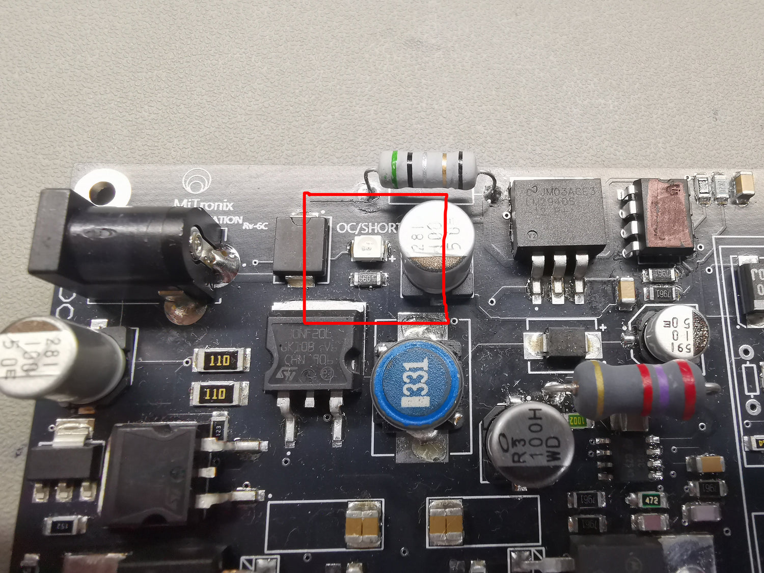
Over Current Protection:
The New versions of OTC12 comes with over current protection. this is to protect the power supply section in case of damaged op amp insertion or in event of power supply short, The OCP is only for Gain-Bandwidth section, As the tester section has its own voltage regulation and current handling. The OCP protection RED led will come on if current draw goes above 70mA or so. In event of OCP please disconnect power to the tester and remover all devices under test and re connect power .
Single / Dual / Quad Package Op Amp tester
Single package tester:
For testing a single package op amps like TL081 , LF356 , OPA627 and others. insert op amp in to single package tester IC socket
Once inserted the LED should start to Flash, this indicates a working / Healthy op amp. if the LED is in OFF state or is permanently ON then this indicates a non functional / damaged op amp. Also check to make sure you have inserted the IC correctly in the right direction as this can result in incorrect results.

Dual package tester:
For Dual package op amps like TL082 , TL072 , LM358 , LF412 and others use the dual package section,
Once inserted the LED should start to Flash, this indicates a working / Healthy op amp. if the LED is in OFF state or is permanently ON then this indicates a non functional / damaged op amp. Also check to make sure you have inserted the IC correctly in the right direction as this can result in incorrect results.
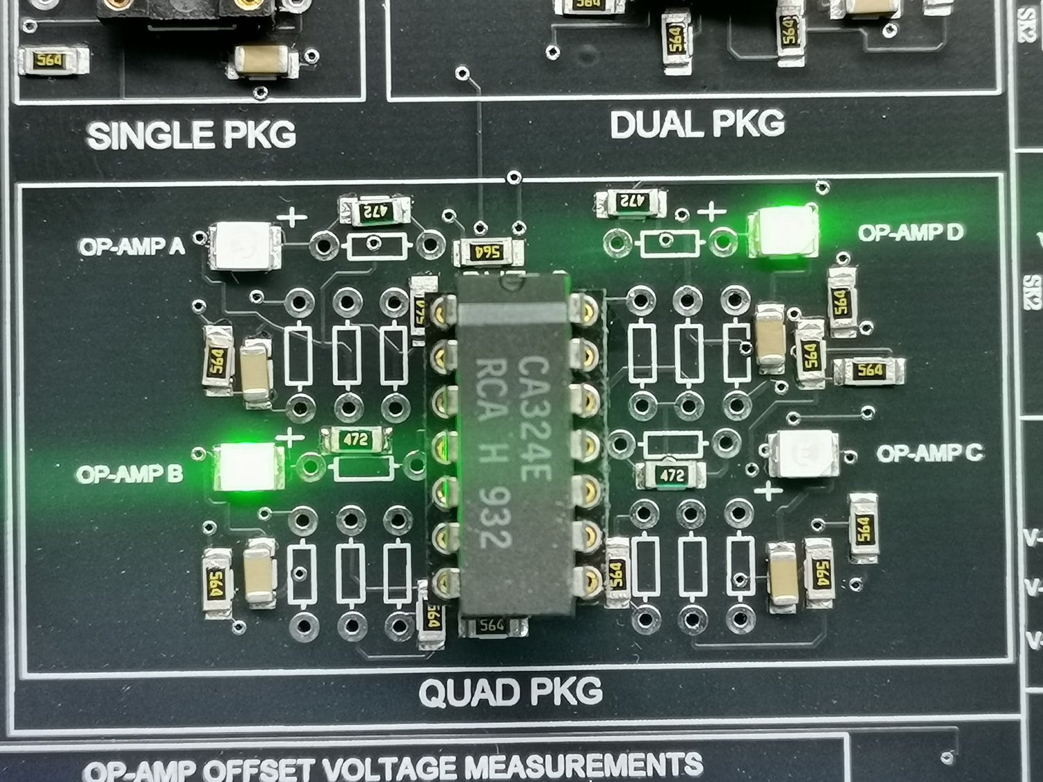
Quad package tester:
For Quad package op amps like Lm324 , TL084 and others use the quad package section,
Once inserted the LED should start to Flash, this indicates a working / Healthy op amp. if the LED is in OFF state or is permanently ON then this indicates a non functional / damaged op amp. Also check to make sure you have inserted the IC correctly in the right direction as this can result in incorrect results.

Gain Bandwidth Measurements Section:
Before inserting op amps and start testing , Make sure you have set the correct power supply voltage for the op amp under test. This is very important as this section has a dual rail supply which can exceed +11v and -11v.
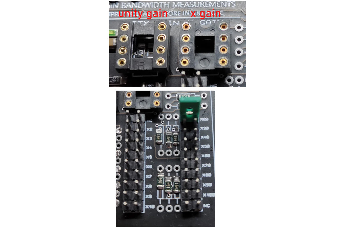
Unity Gain , X Gain:
Once you have set the correct power supply voltages for your op amp you can insert a Single package op amp like TL081 , TL071 LF411 , LF356 , OPA627 in either unity gain socket or X gain socket. Use the Unity gain section to test if your op amp is stable as unity gain / Buffer and upto what frequencies.
To start the test use the signal in section to feed a sine wave in to your unity gain configured op amp , The input is 50 ohms matched but not terminated and is AC coupled. Once signal is feed to DUT use the signal out to measure the signal against the input signal to see the specs of unity gain configured op amp
Make sure you have set the levels correctly and that the op amp do not saturat agains its power rails. As this can give false readings. Also make sure you have set the signal in VPP to a reasonable value so to see exactly what gain can your op amp provide, because if signal in is high in voltage then the maximum gain can push the op amp to its saturation on power rails,
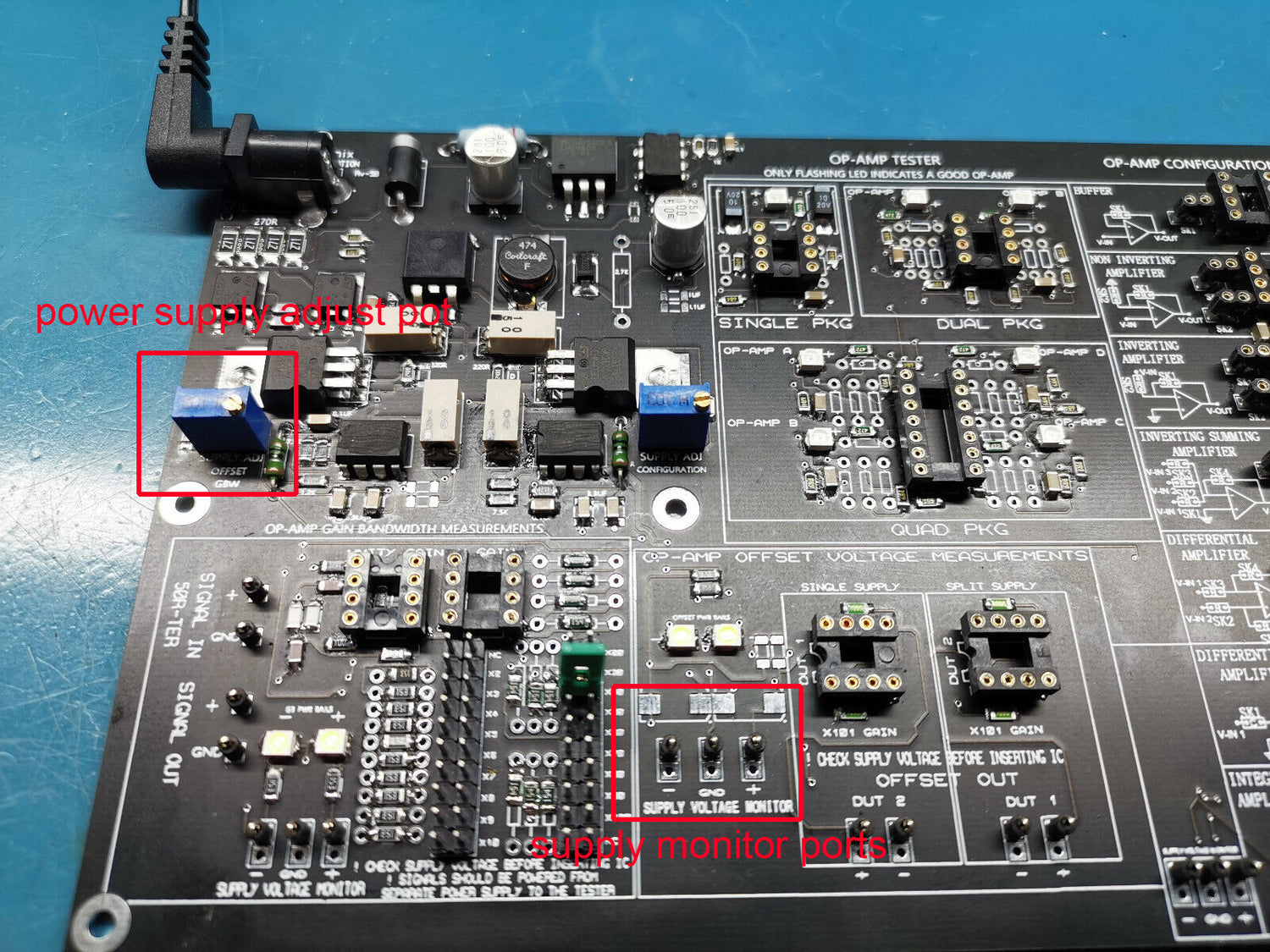
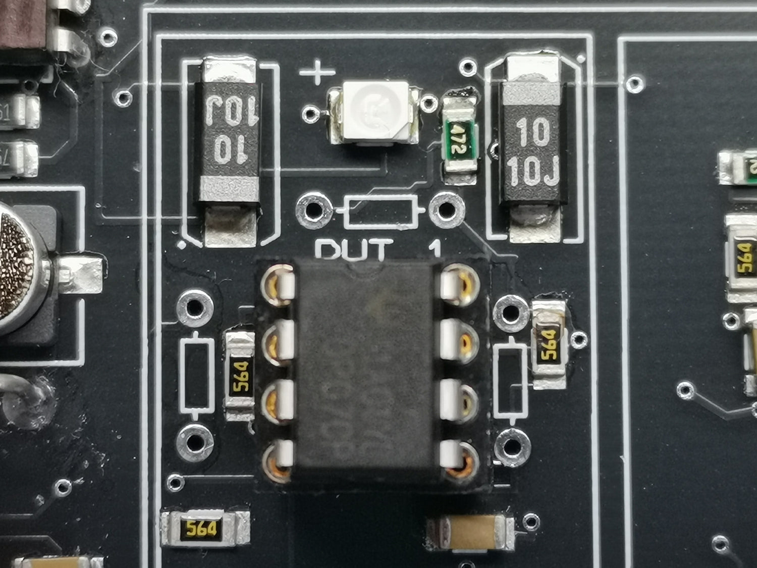
Offset Voltage Measurements Section:
Before inserting op amps and start testing , Make sure you have set the correct power supply voltage for the op amp under test. This is very important as this section has a dual rail supply which can exceed +11v and -11v.

Measuring Offset Voltage:
Use this section to measure op amps offset voltage. There are two socket for this section, Single supply or dual supply. Refer to your op amp to see which one is supported , If your op amp can operate in single supply mode and dual supply mode then you can test it in both socket to see what results you will get ,The gain for the offset has been set with precision resistors to around X101. Use the Offset out ports to monitor the voltages to see the specs of your op amps under test.

Op Amp Configuration Power Supply:
Before inserting op amps and start test make sure you have set the correct power supply voltage for the op amp under test.This is very important as this section has a dual rail and single rail supply which can exceed +12v and -12v.
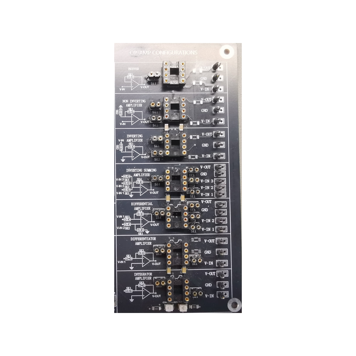
Op Amp Configuration Section:
Use this section to test op amps in different configuration. This section is designed only for a single package op amp. Note that this section signal in and out are not AC coupled. If you are feeding an AC signal make sure you AC couple it in or it will produces a false reading on output.
